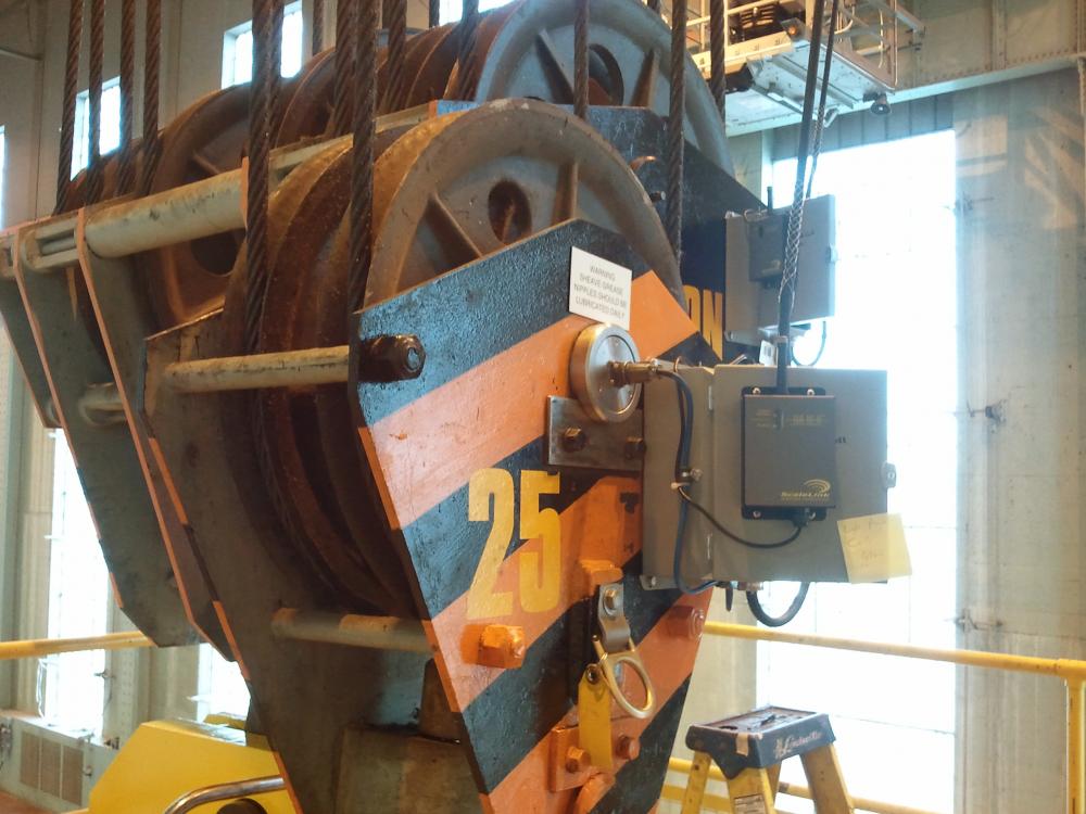
 From mining and manufacturing to construction, transportation, and agriculture, the need to weigh or measure inputs, outputs, and applied force has grown in recent decades to improve production safety and control costs.
“Design engineers are responding as complex systems such as mine lift equipment, construction cranes, industrial tanks, grain silos, and locomotives—which may have lacked weight or force sensing capability in the past—are being upgraded to include load pins, load cells, and tension cells,” says Riley Phillips, a mechanical designer at Massload, Saskatoon, Canada. “These sophisticated weight and force sensing devices can help to maximize production load efficiency while offering some of the enhanced safety features that are increasingly required by regulation, such as automatic shutdown if a load exceeds capacity.” What follows is a quick primer on what design engineers need to know about measuring weight or force with load cells, load pins, and tension links.
Understanding the basics
A load cell is a transducer that changes force into a measureable electrical output. There are many varieties of load cells, of which strain gauge-based varieties are the most common. Load cells can range from a versatile singleended shear beam, which can be used in weighing applications such as blenders, hoppers, and floor scales, to double-ended shear beams that can be used in applications such as tank weighing and large capacity platforms.
“Load pins and tension links are actually sub-categories of load cells,” explains Phillips. “Load pins can be substituted anywhere there is a structural pin, and there’s a need to know the shear force on it. Tension links are a type of load cell that measures force in tension applications, such as cables, chains, and pulleys. These are often used in lifting, pulling, and winching applications such as for cranes, line wire tension, and man safety cages in mines.”
Standard load cells and tension links are typically used if the system is standard or an engineer can adapt the system to an off-the-shelf item. This tends to occur in applications where there’s some design flexibility in the early stages of design. Most load cells, load pins, and tension links are custom when they must be adapted to fit existing systems. Additionally, designers should consider the benefits of custom load cell solutions for new designs where their use enhances the overall system integrity, safety or performance.
Avoiding pitfalls
Planning a superior weighing system or retrofitting an old one on existing equipment can present challenges to even veteran design engineers. Bringing in a weighing system vendor during the planning stage can allow safety improvements and controlled costs while meeting any code requirements.
“There are a lot of issues,” says Nathan Heppner, mechanical engineering team lead at Massload. The important thing is to look at the design process upfront to maximize reliability and manufacturability while minimizing cost. “For instance, fit is critical on load pins because they normally have to interface with tight tolerances,” adds Phillips. “Depending on where the load is applied, if the supports, loading area, pin diameter, or other factors are off, the load pin may not work as expected.”
To avoid pitfalls, it is advisable for engineers to insist on a regulatory-approved quality management system that traces the load cell manufacture at each critical step from start to finish. Engineers should also request a design flow checklist from any weighing system vendor to ensure that nothing critical or even desirable is missed.
“CAD modeling is not always straightforward, and sometimes you have to think beyond software’s presentation,” adds Phillips. “A stress concentration in the CAD modeling may look artificially high in one area, but may be masking a stress pattern in another area. You need accurate data on stress patterns throughout the component.”
Design engineers would benefit from asking the weighing system vendor to validate the output of their load cell component against simulated real-world conditions. This could be done by simply requesting a digital photo of the test setup, when possible, for enhanced accountability.
“The design specifications, loading, testing, and application must be aligned,” explains Heppner. “A mistake as simple as modeling with the wrong supporting restraints could artificially strengthen load pin CAD results. If testing doesn’t catch it, the component may not perform at its stated capacity.”
To ensure output stability, engineers also need to know how the load cell output may vary depending on material strain over time, says Phillips. Conducting a creep test to determine how stable the output is over time can also be important.
The right vendor partner will also pay attention to small details that will streamline manufacture of the weigh system component, according to Phillips, such as bonding, grounding, sealing, and gauge selection to ensure lasting performance and resistance to water intrusion.
Phillips points to the importance of knowing the correct location where load cells, load pins, or tension links are supported “because if you over support a load cell it won’t have the output you’d expect.” Placement of internal electronic components such as bondable or trimmable resisters can also affect device performance, he says.
Details such as the types of bolts used should not be overlooked. “The customer may require a countersunk bolt arrangement to hold lids on, if during operation bolt heads could be sheared off because they’re close to walls or equipment.”
“Even details such as putting scribe lines on where to place components can ease manufacturing,” says Phillips.
As design engineers respond to the growing need to weigh or measure inputs, outputs, and applied force to improve production safety and control costs, working and consulting with the right vendor partner can be a critical choice in designing weigh systems with the optimum load cells, load pins, or tension links.
Author; Unknown
Source:

